This article introduces Gray code, a specialized binary arrangement necessary for absolute encoders to communicate with controllers.
Computer processors that run virtually all modern control systems speak in a unique language. Values of on/off relate to the ‘binary’ system, usually represented as 1 and 0. This system works well for most industrial sensors, but one common device — the encoder — presents some unusual challenges that require a rather specialized binary arrangement to communicate with a controller. This is known as Gray code.
The Role of Encoders in a System
Motion is probably the most common connecting factor between all areas of manufacturing, processing, and distribution. It’s difficult to find any industrial facility that doesn’t include a conveyor, robot, or automated motion process of some kind. Controlling the motion requires some level of feedback to verify that the required motion happened at the right time. For rotary motion (motors), this feedback is usually in the form of an encoder.
There are two kinds of encoders: incremental and absolute.
As a simple comparison, incremental encoders track transitions between light and dark marks around the edge of a rotating disk.
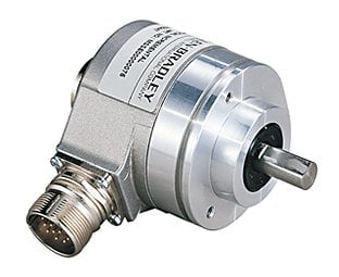
Figure 1. The 844D High-Frequency encoder is an example of an incremental encoder.
They are very precise and fast, but since they are identical all the way around the disk, the only information that can be obtained is how fast the disk is moving and how far it has gone in a given amount of time, like watching fenceposts out of a car window while driving.
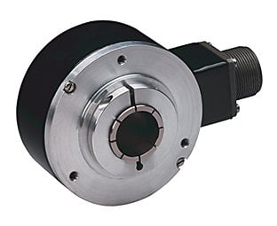
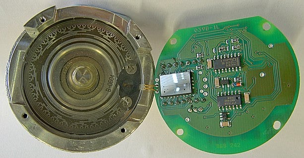
The absolute encoder disk has a complex pattern of light and dark marks radiating from the center to the edge of the disk. The pattern differs depending on where the disk is rotated. The information tells not only how fast and how far the disk is rotating, but also exactly where the disk is positioned at any time, even if power is cycled.

Figure 2. The Bulletin 842A multi-turn magnetic encoder is an example of an absolute encoder.
These absolute encoders have a sequence of sensors in order to read the entire pattern, and since there are multiple sensors, the connected controller must read them all simultaneously to obtain the current positional data.
The Absolute Encoder Timing Problem
Most of these absolute encoders have between 8 and 10 sensors aligned in a row to read the pattern of dark/light marks radiating from the center. This would relate to either an 8- or 10-bit output. At any time, the pattern would consist of some combination between 00000000 and 11111111, at least for the 8-bit output. If the pattern followed a true binary combination, this would be the lowest and highest patterns on the disk, respectively. At some point on the disk, it would transition immediately from the highest back down to the lowest pattern and begin increasing again.
The timing problem occurs if the controller reading those sensors is not able to read them all simultaneously. It starts with the first sensor, and by the time it reaches the eighth or tenth sensor, the best we can hope is that the pattern hasn’t changed since the first sensor reading. If several of the sensors transition from light to dark at once, there is a slim but possible chance that the controller will begin reading the sensors on the old pattern but finish the reading on the new pattern. So, the binary sequence is half old and half new but completely incorrect. This would be interpreted as a wild motion from one position to another which is far away.
If the motion was slow and the controller could read the sensor pattern extremely quickly, the problem might not be very severe. Incorrect readings might still occur, but only once in a long while. However, encoders rotate so quickly that we usually have to select specialty high-speed counter modules to examine and track the readings. Even the speed of typical digital input modules is not fast enough to keep up. This means that those erroneous readings would be expected to occur much more frequently. The result may be a split-second opening of a hydraulic valve to compensate for a perceived ‘error’ (which did not actually happen). The damage to equipment from this action may be catastrophic, so even a rare instance is unacceptable.
Gray Code: The Sensor Arrangement Solution
Slowing down all the motion might be a possible solution, but obviously you can’t just slow down an entire system to achieve better results – that would reduce optimization and efficiency.
The actual solution is far more simple but requires a bit of creativity to understand. This solution is the implementation of Gray code, which involves breaking away from the standard binary counting sequence in order to eliminate the chance of multiple bits changing at one time.
The standard binary sequence gives each bit a weight, much like our decimal system has the 1’s, 10’s and 100’s place, etc. Each time the maximum value of every place is reached, all the places reset to 0 at the next count, so just like if you reach 999, the next value is 1000 which resets all those places back to 0.
In binary, 111 might be one count, then with the next count, 1000, those places all reset to 0. Notice that there are several numbers changing at once — this is the problem with encoders using binary outputs.
Gray code is named after the innovator of the counting system, Frank Gray. It does not indicate any modification of the black/white pattern on the encoder disk. The system does start at 000000 for an 8-bit Gray code, but with each next count, only a single bit may change at any time. That way, the controller can only have two possible readings:
- The sensor array will be read just a moment before the one bit has changed and it will indicate no change.
- The array will be read just a moment after that one bit has changed, and the controller will understand that a small degree of motion has occurred.
Since only one bit can change, there is no chance that the array can be read in the middle of a change where some of the bits have changed properly, while others have not.
Gray Code Implementation
To use this Gray code system in a controller, it must first be understood that only absolute encoders use this sequencing system. In an incremental encoder, there is only one light/dark pattern on the disk, so there is no pattern, only transitions.
Figure 3. Only absolute encoders utilize the Gray code sequencing system.
Gray code is not a counting sequence, so if you were to read this directly as a binary number, it would not appear to be progressing in a circle, and therefore would not give you any usable information about speed or position.
The PLC or other controller using this Gray code input must be set up with a high-speed counter and a tracking formula that converts the Gray code input into a binary equivalent number to accurately send positional data. Some PLCs have this function readily available, but for others, it must be created by the user.
Copyright Statement: The content of this website is intended for personal learning purposes only. If it infringes upon your copyright, please contact us for removal. Email: [email protected]


