Before digital control systems, responses were fairly slow. Push a button, and a motor contactor engaged. These days, the speed of computers introduces some new challenges but brings solutions as well.
In the control system engineering space, it is well known that two different techniques exist for switching purposes, those that are purely mechanical and those that rely on solid-state transistors. While transistors have certainly revolutionized every aspect of engineering, there are a few key disadvantages that cause control engineers to still turn to mechanical pushbuttons and relays for all sorts of tasks, even when solid-state devices are plentiful.
Simply put, solid-state switching requires a complete power supply in addition to the signal wire, creating more wiring, they also carry less current than equivalently priced mechanical switches and therefore cannot handle as wide an array of tasks. Finally, even when switched off, transistors allow a slight leakage of current which may be unfavorable, even if the load is not energized by such leakage current.
Are Mechanical Switches the Best Choice?
Although solid-state devices may present some problems, mechanical switches aren’t perfect either. They are plagued by three main points of concern: they are much slower to respond than transistors, the physical distance between contact points creates an environment ripe for sparks, and finally, our key point today – the mechanical impact of two contact points causes bounce.
What Does Switch Bounce Mean?
When you press a button or turn a switch, a spring-loaded snapping action causes the contacts to immediately shift from open to closed with a ‘click’. This ensures rapid action, but also causes the metal flap of the contact to collide with the stationary contact in the body of the switch. In very slow motion, the contact will hit once, bounce back, then hit again and again until it finally stops bouncing.

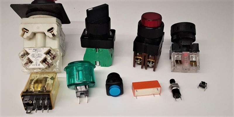
Figure 1. Selection of mechanical switches, relays, and pushbuttons – all prone to debounce issues.
To visualize switch bounce, imagine dropping a bouncy ball on a concrete floor. The initial impact makes the ball bounce back, but not as high. This will bounce several times until the kinetic energy is finally exhausted. Speed up that process to a rate nearly invisible to the eye, and this illustrates switch bounce.
In many circuits, this is not a problem at all. The lights in your house do not respond rapidly enough to experience any effects from this quick on-off-on-off pulse for a moment. Coil-based devices, such as relays, contactors, or solenoids are also immune to this bounce effect since inductors are too slow to respond to fast changes.
The problem arises when devices with input monitors are rapid enough to detect these multiple switching actions and are likely to interpret them as several consecutive button presses.
What sorts of devices are fast enough? Digital inputs for controllers with I/O modules, like PLCs.
When is Switch Bounce Actually a Problem?
Just because a digital input detects a quick flicker, the action on a resulting output may not be influenced by such bounce. If the command is being sent to a relay output module, or if a digital output is driving a coil-based device, the momentary bounce will have no effect.
However, if the digital input is driving a counter, an incrementing math command, or an edge detection command, that rapid switching may significantly impact results, even if it only happens two or three times.
How Do You Debounce a Switch?
This process must always happen externally to the mechanical contact itself, you cannot simply eliminate the switch bounce. There are two primary methods for controlling the effects of switch bounce: hardware and software.
Debouncing with RC Circuits
A common procedure in PCB and prototype solutions is to place a resistor and capacitor in parallel with the switch contacts. When the voltage is applied to the open switch and to the capacitor at the same time, the capacitor charges relatively slowly, allowing the current to flow for a moment, but then blocking it after being charged to the source voltage. The moment the button contact is closed, the capacitor will discharge as current flows through the switch contacts. However, the momentary on-off-on-off of the switch will be eliminated by the draining capacitor.
A design consideration here must emphasize that if a capacitor is used, the voltage will not go from 0 to 24 volts instantly when the button is energized, due to the capacitor. We may have eliminated bounce, but we will also delay the rise time of the voltage signal. Choose the resistor and capacitor combination wisely.
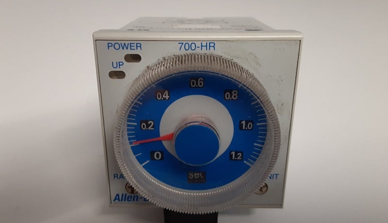
Figure 2. Timer relay, useful for analog circuit debounce reduction.
Debounce with Timers
Digital signal processors, such as PLC inputs, can always take advantage of built-in timers. When an input point is energized, a timer immediately begins, and for a very brief time, no further changes in the input status will be monitored.
This debounce time is critical in real-world operations. With the speed of modern processes, you may have digital inputs attached to high-speed sensors for counting hundreds of items a second. In this case, a debounce of more than just a few milliseconds would be fatal to the operation. Debounce built right into some controllers may be acceptable, as long as the debounce time is shorter than the minimum possible delay between actual expected event triggers. For this reason, it is common for digital inputs to have no integrated debouncing capability.
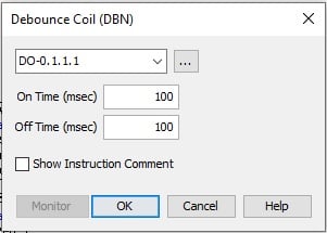
To achieve debounce in software, there may be commands which examine for a rising or falling edge and provide a user-defined time delay before rechecking. This allows each input terminal to be customized with a long, short, or no debounce at all, and can sometimes allow different debounce times between a negative and positive-going command, as shown below.

Figure 3. Software example with built-in debounce capabilities.
If no such command exists, a short combination of two timers can be utilized in a variety of ways. Many examples are found across the internet, but there is one caution when ladder logic is involved.
Many examples use a timer and energize the output at the end of the very short timer duration. This means you press the button, and then have a very short delay before energizing the output. Other methods involve energizing the output at the first moment of contact, then maintaining that status until the input is de-energized. The example below illustrates a debounce for a positive-going signal. For a negative-going signal, a short TOF (off-delay) timer can be used.

Figure 4. Software using a timer to achieve a positive-going debounce.
Summary
The study of electronics and control systems will always lead to unexpected problems as a result of the nature and physics of electricity – nobody can truly predict every failure. A short bit of circuit or code knowledge can help to troubleshoot more than just a few issues.
Copyright Statement: The content of this website is intended for personal learning purposes only. If it infringes upon your copyright, please contact us for removal. Email: [email protected]

