A typical control system uses PNP sensors and tends to be easier to visualize. For opposite polarity systems, the NPN sensor is the only compatible sensor type. Learn more about NPN sensors, including characteristics and uses.
In a typical control system, the primary method of sending input signals to a PLC is by first powering the input device, then upon energization, sending the control voltage to the PLC, which returns it to ground. This system uses PNP ‘sourcing’ sensors and tends to be easier to visualize. For opposite polarity systems, the NPN sensor is the only compatible sensor type. The reason and the potential benefits of these NPN sensors might just outweigh the confusion they create.

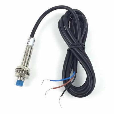
Figure 1. Example of an NPN sensor.
Selecting the right kind of sensor is not an easy job. Not only is there a wide variety of quantities that need to be measured, but each category contains a wide array of sensor types, and they might be analog or discrete. Adding to the complexity, most sensors may be available in a few different wiring choices.
Understanding NPN Sensors
One of the most common pitfalls in sensor selection is understanding the difference between PNP and NPN sensor wiring. The confusion is not due to a lack of knowledge available — a quick internet search will yield countless articles with titles such as ‘Understanding NPN vs PNP Sensors’.
In my own experience, it took me longer to understand NPN sensors, for two reasons. First, PNP sensors supply current to an input module, and the direction of the electrical flow is the same as the flow of information. The transducer measuring the real-world quantity is the information, originating at the sensor and going into the module for instruction processing. The whole process seems natural and logical.
The NPN sensor allows current to flow from the input module through the sensor to ground. It certainly functions correctly when the right hardware is used, but the flow is opposite, therefore adds more confusion.
The second reason that it took me longer to understand these sensors is simply because I wanted to know why they existed. Typical systems will use PNP ‘sourcing’ sensors. Some PLC input modules can be wired for either NPN or PNP sensors, but some are one-way only. I wanted to know why, if one is more popular and is completely functional, why is the other type still available and installed in some systems?
NPN Polarity
The simplest way of describing the operation of an NPN sensor is to break it down into two parts. First, supply power for the sensor. Most often, this is a range of 10-30 volts, so it’s compatible with 12-volt and 24-volt systems. Connect the appropriate wires (usually brown and blue in some order) to the power supply.
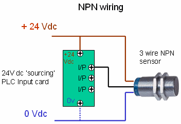
The remaining wire is the signal wire (sometimes called ‘load’ wire). For this NPN sensor, current will flow from the input module through this signal wire as soon as the sensor is energized. The only condition for this to work is that the signal grounds MUST be connected between the input module and the sensor itself in order to complete the circuit.

Connections of the three wires of an NPN sensor.
It may help to visualize the sensor as a check valve. Is its de-energized state, the check valve is closed and nothing will flow. When energized, the check valve opens and allows flow toward the sensor only.
Multiple-Voltage Compatibility
This is the part of NPN sensor wiring which provides a distinct advantage. As long as the sensor is properly supplied with power, any range of voltages can be connected to the signal load wire and still return properly to ground.
To visualize this advantage, assume you have a machine with 12 volts powering all the I/O devices, including the sensors. These input signals must work with a nearby PLC having digital inputs requiring 24 volts. If those sensors were the standard PNP types, they would output the 12 volts to the PLC, not enough to provide a positive signal.
There would be a couple of possible solutions. First, switch all of the I/O power supplies with a 24-volt supply. Second, convert the 12-volt signal to a 24-volt signal with a DC-DC converter. Finally, you could obtain a PLC with 12-volt compatibility. All of these options sound expensive and time-consuming.
A better choice may be to use NPN sensors. In this scenario, they would still be powered with an appropriate 12 volts (within the 10-30 range). The 24 volts would be supplied by the ‘sourcing’ PLC input module, returning to the common signal ground through the sensor. This allows that single PLC module to work with a few NPN sensors in a 24-volt system, right alongside a few NPN sensors in this 12-volt system.
Since the cost of a certain NPN vs PNP sensor is nearly identical in most cases, this solution does not cost any extra money and does not take any additional time to install. The added flexibility of using the multiple voltages side-by-side can relieve an otherwise difficult task.
Copyright Statement: The content of this website is intended for personal learning purposes only. If it infringes upon your copyright, please contact us for removal. Email: [email protected]
