Designing a system with motor motion always includes a consideration of safety. Incorporating safety contactors might be the correct prevention to protect equipment and users but may add additional challenges.
Why Is Switching Power So Important?
Most control panels on equipment with some level of automation will have contactors inside. A contactor is a device that allows a control system to manipulate an electrical circuit’s on or off state. The equipment could be a simple on / off switch for a motor, or it could be advanced automated assembly equipment—both systems will have contactors.

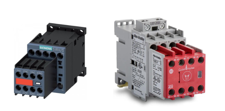
Figure 1. Two models of safety contactor—one from Siemens (right) and one from Allen-Bradley/Rockwell (left).
What Is a Contactor?
Similar to a relay, a contactor is used to break or open an electrical circuit. Unlike relays however, contactors will typically be able to open circuits with multiple poles at the same time and are designed for thousands of volts with a higher current throughput.
Most relays may only be capable of a few hundred volts. Some relays can be soldered directly to a printed circuit board, while others can attach to a rail or panel with other components. While many can control motors, the final power consumption of the load should be limited based on the relays’ specs.
A typical contactor has a coil with positive and negative terminals. These terminals usually take more power than a relay (24 VDC or 120 VAC and sometimes 240 VAC) to energize a coil that closes contacts. The contacts within a contactor are designed to withstand three-phase supply voltages, in some cases reaching into the thousands of volts and hundreds of amps. With the ability to control circuits with much higher voltage and current ratings, the physical size of a contactor is much more than a relay. Each pole will have its own terminal with some contactors having a normally open or closed terminal that is used for monitoring. Contactors are typically used to control the power supply for motors and are sometimes combined with overload protection relays to become motor ‘starters’.
Contactors can also be used to control supply power to other equipment, servo motors, smaller electrical panels, or other automation equipment such as robots. Additional auxiliary (aux) contacts can be purchased and added to the contactor. These auxiliary contacts are used to monitor the state of the contactor and are rated for much less amperage. Alarms or faults can then be generated within the control system to let maintenance staff or operators know that a contactor is not operating as expected.

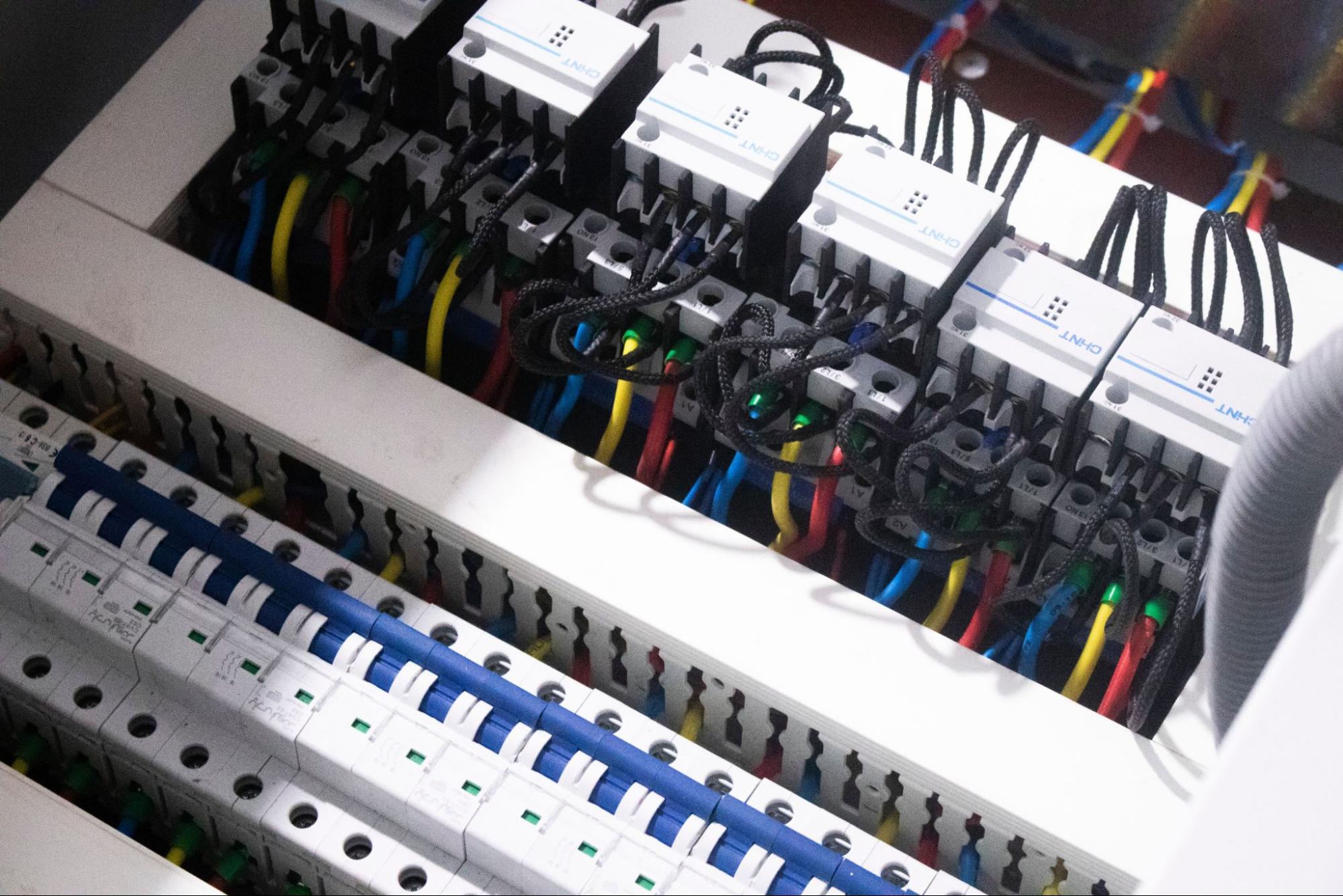
Figure 2. Contactors (both standard and safety models) can be found in long lines inside many machine control centers (MCCs).
What Is a Safety Contactor?
A safety contactor has the same role and functionality as a regular contactor except that its contacts are mechanically linked together so that all three poles’ contacts will close together and will fail in an open state. If a safety contactor fails, the control voltage will be applied but the contacts will not close. If an auxiliary contact is used to monitor the contactor state, the control system will be able to notify the operator of the failed contactor and the safety system will not energize.
Allen-Bradley’s safety contactor product line all have a red face plate to signify they are safety-rated contactors, but not all manufacturers use the same color code. Siemens offers a line of safety contactors as well, but they come in the standard Siemens color, sometimes with a yellow or red indicator plate on the front of the contactor. Both examples can be seen in Figure 1 at the top of the article.
Other companies only offer force-guided or fail-safe contactors which satisfy the requirements for safety contactors. Safety contactors are not only used with motors—in some automation equipment, dual safety contactors control the 24 VDC power to other automation devices such as pneumatic valve banks, or STO signals for robots. This style of safe control is referred to as ‘switched power’. Devices that provide motion within the machinery can be powered using switched power, then when the safety circuit is open, those devices will no longer have power to operate.

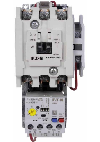
Figure 3. Eaton standard contactor with motor overload relay. Eaton employs a bright yellow color to denote ‘safety’ rating, so this is a standard model.
Industrial Applications – Safety vs Standard
When designing equipment, deciding when to use a safety contactor or a regular contactor is very simple. Safety contactors open when the matching safety circuit is energized. This happens when an emergency stop button is pressed, a light curtain is broken, or a door to the machinery is open.
The frequency of cycles on a safety contactor is generally very low. Once the machinery has control power, devices can be safely controlled using a standard contactor. If a standard contactor fails in the closed position, simply opening the safety circuit will stop all the devices connected to that circuit.
When Should You Use Safety Contactors?
When designing safety circuits with safety contactors, some safety ratings, such as Category 3 safety, require dual contactors, meaning the control voltage needs to travel through two contactors in series. This way, if a contactor fails to operate, as expected, there is still another contactor that can open the circuit in an emergency.
Some equipment designers simplify their electrical designs by only using fail-safe contactors within the electrical system for safe and non-safe circuits. This makes for a smaller bill of materials and a more robust system as fail-safe contactors are designed to take more abuse and will always fail in an open or safe state.
When deciding the proper cases to use a safety contactor or a standard contactor, refer to when you want to control the device. If the operation of the device is always identical to the safety circuit (machine on when the safety circuit is on), then a safety contactor is your best choice. If you need to change the state of your device before or after the safety circuit is energized, then you will need a standard contactor. However, keep in mind that other machine design regulations may still require the use of a safety contactor on the control voltage branch.
Safety Contactor Design
Many devices exist for the single purpose of switching power on and off. This makes the choice of devices more difficult based on machine operation specs. Both relays and contactors can be purchased on ‘standard’ and ‘safety’ versions.
These safety contactors are useful in those cases when machine power or individual motor operation must be reliably and securely switched off in the case of any emergency situation.
For more information about contactors, relays, and safety relays, check out the articles below:
- Introduction to Safety Relays
- Contactors versus Relays – Differences and Applications
- Understanding the Differences Between Protection Relays vs Control Relays
Copyright Statement: The content of this website is intended for personal learning purposes only. If it infringes upon your copyright, please contact us for removal. Email: [email protected]
